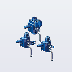
Integrated Hydraulic Accumulator Safety & Isolation Solution
An accumulator safety and shut-off valve block is an integrated hydraulic manifold installed directly between a hydraulic accumulator and the working system. It consolidates circuit isolation, controlled depressurization, over-pressure safety relief, and pressure monitoring into a single compact manifold assembly. Designed to support ISO 4413 system safety principles, SCHWERLL oil-side safety valve blocks (commercial series AJS) protect service personnel during accumulator maintenance, safeguard fluid circuit integrity, and offer optional solenoid-operated automatic unloading for emergency shut-down integration.
               [ HYDRAULIC ACCUMULATOR ]
                           │
                           ▼ Port A (Accumulator Port)
     ┌─────────────────────────────────────────────────────┐
     │          SCHWERLL AJS SAFETY VALVE BLOCK            │
     │                                                     │
     │  [ Manual Isolation Ball Valve ]───────► Port P     │ (To Main System / Pump Circuit)
     │  (Quarter-Turn with Optional Padlock)               │
     │                                                     │
     │  [ Safety Relief Valve Cartridge ]─────► Port T     │ (Safe Reservoir / Tank Return)
     │  (Adjustable Over-Pressure Relief)                  │
     │                                                     │
     │  [ Manual Needle Bleed Valve ]─────────► Port T     │ (Controlled Oil Decompression)
     │  (Fine Throttling Discharge to Tank)                │
     │                                                     │
     │  [ Pressure Test / Gauge Coupling ]────► Port M     │ (Test Point / Pressure Gauge Port)
     │                                                     │
     │  [ Optional 2/2 Solenoid Dump Valve ]──► Port T     │ (Electrical E-Stop Decompression)
     └─────────────────────────────────────────────────────┘
* Illustrative functional architecture — exact port arrangement, valve cartridge configuration, and port markings depend on the selected AJS model and approved hydraulic drawing.
Port Function & Connection Designations
* Illustrative port markings based on standard hydraulic circuit practice; exact port markings and interface dimensions depend on the selected AJS model and approved drawing.
| Port | Designation | Connection Types | Functional Circuit Routing |
|---|---|---|---|
| Port A | Accumulator Connection | Threaded or Flange (per spec) | Hydraulic inlet connecting to the accumulator fluid port or accumulator mounting adapter. |
| Port P | System / Pressure Line | Threaded or Flange (per spec) | Primary outlet connecting the isolated accumulator circuit to the main hydraulic power circuit. |
| Port T | Tank / Drain Return | Threaded Drain Port | Depressurization return safely discharging over-pressure relief fluid and manual bleed oil to reservoir. |
| Port M | Pressure Gauge / Test Point | Test Coupling or Gauge Thread | Diagnostic port for permanent analog dial gauge, electronic pressure transducer, or portable test coupling. |
Core Integrated Safety & Control Functions
1. Accumulator Isolation
Quarter-turn manual ball valve enables physical separation of the accumulator from the active hydraulic circuit, providing tight shut-off isolation in accordance with the selected valve seat specification.
2. Controlled Depressurization
Integrated fine-throttling needle bleed valve allows maintenance technicians to vent trapped oil from the accumulator side back to tank in a gradual, controlled manner, preventing pressure shocks and oil spray.
3. Over-Pressure Relief Protection
Direct-acting or pilot-operated safety relief valve cartridge protects the accumulator and circuit from hydraulic pressure spikes. The relief-valve setting is configured to the accumulator and system protection requirements, and must remain within the allowable pressure limits of connected equipment.
4. In-Line Pressure Monitoring
Dedicated gauge / test port (Port M) allows connection of an analog dial gauge or electronic pressure transducer, enabling visual verification of stored pressure prior to servicing.
5. Optional Solenoid Unloading
Electrically operated 2/2 directional poppet valve can be integrated with emergency-stop circuits or safety PLCs to initiate automatic accumulator depressurization when de-energized; discharge time depends on accumulator volume, system pressure, fluid viscosity, and valve flow capacity.
6. Lockout / Tagout (LOTO) Support
Optional lockable handle structure allows padlock attachment in the closed position, supporting facility energy-control and lockout/tagout (LOTO) procedures once residual pressure has been fully bled.
SCHWERLL AJS Series Model Selection & Specifications
| Model Series | Nominal Bore (DN) | Pressure Capability | Relief Protection Setting | Connection Interface | Actuation & Optional Features |
|---|---|---|---|---|---|
| AJS-10 | DN10 | Up to 800 bar family capability | Configured per accumulator MAWP | Threaded / Flange (per spec) | Manual / Solenoid Unloading |
| AJS-20 | DN20 | Up to 800 bar family capability | Configured per accumulator MAWP | Threaded / Flange (per spec) | Manual / Solenoid / Position Switch |
| AJS-32 | DN32 | Up to 800 bar family capability | Configured per accumulator MAWP | Threaded / Flange (per spec) | Manual / Solenoid / Position Switch |
| AJS-40 | DN40 | Up to 800 bar family capability | Configured per accumulator MAWP | Threaded / Flange (per spec) | Manual / Solenoid / Position Switch |
| AJS-50 | DN50 | Up to 800 bar family capability | Configured per accumulator MAWP | Threaded / Flange (per spec) | Manual / Solenoid / Pilot Control |
* Technical basis: Model designations DN10–DN50, published family maximum working-pressure capability up to 800 bar, actuation forms, and optional features are based on SCHWERLL corporate capability documentation (《西维尔公司简介 2025》 p.6). SCHWERLL corporate documentation lists a maximum working-pressure capability up to 800 bar for the oil-side safety shut-off block family; the allowable working pressure of the selected DN and configuration must be confirmed on the model-specific drawing or quotation. Port connection standards, relief setting calibration, and dimensions are confirmed against approved engineering drawings at RFQ.
Flow Capacity & Relief Pressure Setting Rules
- Flow Capacity Selection: The nominal bore (DN) and valve flow capacity must be matched to the peak accumulator discharge flow rather than average pump delivery. Flow capacity and allowable pressure drop must be selected against accumulator discharge flow; request engineering confirmation for high-flow duty.
- Relief Setting vs. Working Pressure: The safety relief valve set pressure must not be confused with normal operating pressure. Relief-valve setting is configured to the accumulator/system protection requirement and must remain within the allowable pressure limits of the connected equipment. The exact set pressure is confirmed at the quotation stage.
- Lockout / Tagout (LOTO) Procedures: Lockable isolation options can support site lockout/tagout procedures. Site personnel must ensure complete energy isolation by verifying zero pressure on the gauge port and executing manual decompression via the bleed valve before affixing safety padlocks.
- Solenoid Unloading Dynamic: Solenoid unloading can be integrated with an emergency-stop circuit to initiate automatic depressurization; actual discharge time depends on accumulator volume, system pressure, fluid viscosity, and valve flow capacity.
Materials, Fluids & Quality Inspection Scope
Materials & Fluid Media
- Body Construction: Body material is selected by pressure class, hydraulic fluid, and corrosion environment (e.g. forged steel or application-specific alloys); confirm the available AJS material configuration at RFQ.
- Operating Temperature: Operating temperature capability range is -40°C to +120°C per SCHWERLL corporate documentation. Seal compounds are selected according to hydraulic fluid, operating-temperature range, and selected valve components; final material specification confirmed at RFQ.
- Fluid Compatibility: Mineral hydraulic oils (HLP/HVLP), synthetic fluids, water-glycol fluids (HFC), and eco-friendly fluids.
Factory Quality Inspection Scope
- Pressure Integrity Testing: Hydrostatic pressure-integrity testing can be performed on manifold block bodies according to project inspection scope. (AVAILABLE / PROJECT-SPECIFIC)
- Seat Tightness Verification: Valve seat tightness checks can be conducted on isolation and bleed valves per applicable valve specification. (AVAILABLE / PROJECT-SPECIFIC)
- Relief Setting Calibration: Relief valve cracking pressure calibration and setting verification can be provided upon order specification. (AVAILABLE / PROJECT-SPECIFIC)
- Material Documentation: EN 10204 3.1 material documentation can be provided where specified in the order and applicable to the pressure-retaining material scope. (PROJECT-SPECIFIC / UPON REQUEST)
17-Point Buyer Specification Checklist for Fast RFQ
To configure and quote an AJS manifold assembly, please provide the following technical parameters:
Compatible Accumulator Series & Engineering Integration
SCHWERLL AJS safety and shut-off valve blocks are engineered for direct or line mounting with all standard gas-loaded hydraulic accumulator configurations:
- Bladder Accumulators: Compatible with standard bladder accumulator units (BAK, BAKM, and BAKH series) for energy storage and pulsation dampening.
- Standard Piston Accumulators: Seamlessly mounts to standard piston accumulator systems in industrial power units and metallurgy installations.
- High-Pressure Piston Units: Engineered integration with high-pressure piston accumulator vessels with pressure ratings confirmed per project configuration.
Maintenance Best Practices: Always execute complete accumulator isolation before precharge service and follow the safe accumulator charging and service procedure when checking nitrogen pressure. For preliminary gas sizing verification, consult our hydraulic accumulator volume sizing calculator.