Hydraulic Accumulator System for EAF / LF Electrode Regulation
SCHWERLL engineers hydraulic accumulator systems for EAF and LF electrode regulation, supporting transient hydraulic demand, manifold integration and engineering sizing.
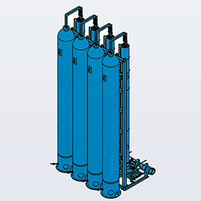
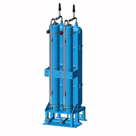
Hydraulic accumulator bank, safety shut-off manifold, and pressure monitoring subsystem supporting EAF / LF electrode-regulation hydraulic circuits (Illustrative functional architecture — actual circuit and control logic depend on furnace OEM design).
Operational Focus & Value Proposition:
Engineered to provide stored hydraulic energy and pressure stability for EAF and LF electrode regulation circuits, supporting high transient flow demands during rapid electrode repositioning without claiming complete furnace or arc-regulator scope.
In the fluid power architecture of electric arc furnace (EAF) and ladle furnace (LF) steelmaking, an engineered accumulator power subsystem is integrated into the electrode-regulation hydraulic circuit to provide pressure stabilization and support dynamic fluid delivery. Under normal operating conditions, rapid electrode adjustments demand instantaneous transient fluid volumes that can exceed direct pump delivery. Stored hydraulic energy in the accumulator bank provides localized power to support rapid transient demand and OEM-defined motion sequences, such as emergency electrode retraction or safe furnace holding, subject to validated capacity and furnace safety logic.
Accumulator bank capacity is sized from actuator displacement, required operating sequence, P₁/P₂ pressure envelope, peak flow and available recharge time; no universal EAF/LF bank volume applies. Accumulator sizing and gas pre-charge parameters are engineered to deliver the required usable fluid volume within allowable pressure limits while optimizing equipment envelope within the melt shop.
How the Accumulator Supports Electrode Regulation
Electrode regulation requires fast, coordinated movement of heavy mechanical columns to maintain optimal arc length, electrical stability, and process control. The fluid power and control architecture operates through two clearly separated paths:
Control & Feedback Path: Electrical / Process Measurements → Arc Regulation Controller → Valve Command → Electrode Motion → Process Feedback
*Illustrative functional architecture — actual circuit topology, valve arrangement, and control logic depend on the furnace OEM design. The hydraulic accumulator does not send control signals to the arc regulator.
In modern steel mill installations (including facilities interfacing with OEM automation platforms such as Danieli Q-REG, Primetals, or Tenova control suites), the digital arc regulator monitors electrical arc variables and commands the hydraulic valves. The accumulator bank acts strictly as a hydraulic energy buffer and pressure stabilizer on the fluid power line—it does not generate control signals or send feedback to the arc-regulation controller. Hydraulic pressure stability and responsive actuator supply support the wider electrode-regulation loop; arc-performance results ultimately depend on the complete electrical, hydraulic, mechanical, and automation system.
Core Functional Roles of the Accumulator Subsystem
Rather than generalized claims of energy reduction, the accumulator subsystem provides four clearly defined fluid power functions in metallurgical furnace operations:
Peak Hydraulic Flow Support: Delivers instantaneous stored fluid energy to satisfy high peak flow demands during rapid electrode acceleration, preventing starvation of high-response servo or proportional control valves.
Circuit Pressure Stabilization: Moderates transient line pressure fluctuations caused by rapid valve transitions and abrupt load reversals during furnace operations.
Pump Load Decoupling: When the furnace operating cycle provides adequate recharge intervals between electrode repositioning sequences, accumulator storage can reduce instantaneous pump-flow requirements compared to direct pump-only delivery.
Predefined Reserve Motion: Stored hydraulic energy can provide a local reserve for predefined hydraulic movements (such as controlled electrode retraction upon primary pump delivery interruption), subject to validated accumulator capacity and OEM safety logic.
Responsibility Boundary & System Scope
To ensure precise procurement specifications and engineering alignment, the responsibility boundary between SCHWERLL and the furnace OEM / automation contractor is delineated below:
Subsystem / Component
Functional Role
SCHWERLL Scope
Furnace OEM / Automation Scope
Hydraulic Accumulator Bank
Primary stored hydraulic energy & pressure stabilization buffer (sized per project duty)
SCHWERLL Sizing & Supply (Piston / Bladder)
Envelope & installation review
Safety & Shut-Off Manifold
Isolation, pressure relief, and controlled decompression relevant to ISO 4413 hydraulic safety requirements
SCHWERLL Design & Supply
P&ID interface confirmation
Fluid-Side Distribution Manifold
Header distribution to individual phase valve stations
SCHWERLL Engineering & Supply
Piping connection interface
Pressure & Level Monitoring
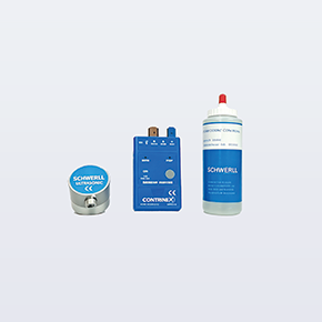
Pressure monitoring; optional piston-position monitoring where a piston accumulator and compatible sensing configuration are selected
Mechanical structural guidance for graphite electrodes
Excluded
Furnace OEM / Fabricator Scope
Arc Regulation Controller
Arc impedance / power control algorithm & valve command
Excluded
Automation OEM Scope (e.g. Q-REG)
Furnace Shell, Transformer & Busbars
Furnace structure, electrical supply, and melt containment
Excluded
Furnace Builder / EPC Scope
EAF vs. LF Duty Cycle & Environmental Factors
Electric Arc Furnaces (EAF) and Ladle Furnaces (LF) present distinct operating regimes that dictate accumulator bank engineering:
EAF Melting Duty: Characterized by frequent scrap movement, bore-in transitions, and dynamic arc hunting requiring rapid, high-frequency transient electrode positioning. The environment involves elevated radiant heat, severe particulate dust, and mechanical vibration.
LF Refining Duty: Involves a liquid steel bath with steady arc conditions, lower mechanical volatility, and continuous chemical homogenization where electrode movements are smoother but require precise position holding.
Fluid & Thermal Compatibility: Hydraulic fluid, fluid temperature, ambient temperature and seal compatibility must be confirmed from the furnace OEM hydraulic specification and selected accumulator / valve components. Fire-resistant hydraulic fluids may be required by the plant’s fire-safety specification, but are not assumed as a universal EAF/LF configuration.
Accumulator Technology Selection: Piston vs. Bladder
Both accumulator technologies fulfill distinct operational roles, selected according to project engineering requirements:
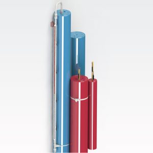
Piston Accumulators: May be selected for larger usable-volume, packaging, or continuous piston-position monitoring requirements (such as SCHWERLL’s published single-vessel capability up to 1,500 L). Final sizing and volume configuration are calculated per project motion sequence.
Bladder Accumulators: May be selected for compact local transient-energy storage or dynamic pulsation-control duties adjacent to valve stands. Final technology selection depends on usable volume, pressure ratio, cycle duty, fluid, temperature, installation envelope, and maintenance requirements.
Safety & Shut-Off Valve Blocks: Provide isolation, controlled depressurization, and over-pressure protection functions relevant to ISO 4413 hydraulic-system safety requirements.
Fluid-Side High-Pressure Manifolds: Custom CNC-machined distribution manifolds streamline accumulator station interconnects and valve-stand integration.
Engineering Sizing & Procurement Checklist
To initiate a comprehensive sizing review for EAF or LF electrode regulation accumulators, customers may submit the following operational parameters:
Furnace Classification: Electric Arc Furnace (EAF) or Ladle Furnace (LF); furnace tapping capacity (tonnage).
OEM & Controller Context: Furnace builder / system integrator (e.g. Danieli, Primetals, Tenova, SMS, or custom) and regulation architecture if known.
Electrode Actuator Dimensions: Cylinder bore diameter, piston rod diameter, and stroke length per phase.
Motion Velocity & Duty: Required raising and lowering speeds (mm/s or m/min); maximum acceleration rate.
Pressure Parameters: Maximum operating hydraulic pressure (P₂), minimum allowable operational pressure (P₁), and safety relief valve setting. (Pressure is defined per furnace OEM specification).
Fluid Volume Requirements: Required transient fluid volume per motion cycle (ΔV) or detailed actuator stroke sequence. (If ΔV is unknown, SCHWERLL engineers can calculate required volume from cylinder geometry and motion timing).
Continuous Pump Supply: Total installed pump flow rate (L/min) and available recharge interval between dynamic regulation events.
Hydraulic Medium: Fluid type (Mineral oil, HFC water-glycol, or synthetic ester HFD-U) and working fluid temperature range.
Ambient Conditions: Melt shop ambient temperature at valve station, radiant heat shielding requirements, and filtration grade.
Pressure-Vessel Code Review: Applicable requirements may include ASME Section VIII, EU PED conformity assessment, or China pressure-equipment regulatory requirements, depending on configuration and destination; inspection documentation (such as 3.1 Material Test Reports or witness inspection) reviewed per project ITP.
In an EAF or LF electrode-regulation circuit, the accumulator bank acts as a hydraulic energy storage and pressure-stabilization subsystem. It delivers transient flow rates during rapid electrode acceleration, moderates dynamic pressure fluctuations caused by fast-switching valves, and provides stored hydraulic energy for predefined emergency movements if primary pump flow is interrupted.
No. SCHWERLL supplies the hydraulic accumulator vessels, safety shut-off manifold blocks, and pressure instrumentation. The arc regulator (such as Danieli Q-REG, Primetals, or Tenova automation packages) is an electrical and process control suite that measures electrical arc parameters and commands the hydraulic valves. SCHWERLL's accumulator subsystem provides the stored hydraulic power that enables the physical actuators to execute those commands smoothly.
Required accumulator bank volume is determined from actuator displacement (cylinder bore, rod diameter, stroke), required operating sequence, P1/P2 allowable pressure envelope, peak flow, polytropic gas behavior, and available pump recharge time. No universal EAF/LF bank volume applies; each system is sized to the furnace OEM motion profile.
Yes. Piston accumulators may be selected for larger usable-volume, packaging, or position-monitoring requirements. Bladder accumulators may be selected for compact local transient-energy or pulsation-control duties. Final technology selection depends on usable volume, pressure ratio, cycle duty, fluid, temperature, installation envelope, and maintenance requirements.
Operating hydraulic pressure is defined by the furnace OEM and electrode-regulation hydraulic specification, rather than a universal standard. Sizing reviews evaluate the customer's specified maximum pressure (P2), minimum operational pressure (P1), and pre-charge pressure (P0) to ensure adequate fluid volume delivery across the complete furnace operating cycle.
Need EAF / LF Electrode Hydraulic Accumulator Sizing?
Our metallurgical engineering division provides accumulator sizing, transient flow support review, and safety manifold integration per furnace OEM hydraulic specifications.
In applications subjected to cyclic stresses, the safety and failure life of metallic or other material components under operating conditions depend on...
In accordance with the IEC 61362 standard of the International Electrotechnical Commission, hydraulic‑electrical servo control systems with redundant design are required for...
Request an Engineering Quote & Technical Specifications
Target Engineering Workflow: Inquiry review confirmed promptly • Preliminary sizing support • Formal quotation & drawings per specification review.
🍪 Cookie & Analytics Notice: We use essential cookies to operate our site and optional analytics to measure accumulator sizing calculator usage and improve fluid engineering services. You can adjust your choice at any time. Learn more in our Privacy Policy.