Subsea ROV Intervention Hydraulic Accumulator System
SCHWERLL engineers subsea ROV intervention hydraulic accumulator systems for BOP control, local stored-energy supply, pressure monitoring and emergency hydraulic functions.
⚡ Hydraulic Power:Stored Subsea Reserve
⏱ Response Dynamic:BOP Function Sized
🛡 Code Alignment:API 53 & API 17H Review
📦 Pressure Vessels:Engineered per Project Code
📐 Hydraulic Circuit Architecture & System Integration
Subsea ROV Architecture
Subsea accumulator bank, safety shut-off manifold, ROV intervention interface, and BOP hydraulic actuator integration.
Operational Focus & Value Proposition:
Engineered to provide an independent, high-pressure subsea hydraulic energy reserve for rapid BOP intervention and secondary emergency actuation without relying on surface umbilical pump delivery.
Subsea ROV-Assisted BOP Intervention Hydraulic Energy Storage System
A subsea ROV intervention hydraulic accumulator system is an engineered fluid-power energy storage assembly installed on a subsea Blowout Preventer (BOP) stack, Lower Riser Marine Package (LMRP), or dedicated auxiliary intervention skid. It provides an autonomous, local reserve of pressurized hydraulic fluid capable of executing critical well-control functions—including opening and closing blind shear rams, sealing pipe rams, operating mechanical ram locks, and unlatching riser connectors—during secondary subsea intervention operations conducted by a Remotely Operated Vehicle (ROV).
Operating independently of real-time surface umbilical fluid delivery, the subsea accumulator bank eliminates dynamic fluid lag caused by thousands of meters of umbilical friction. The system integrates accumulator pressure vessels engineered for applicable project code requirements, dedicated safety isolation and relief manifolds, high-pressure distribution piping, and project-coordinated ROV intervention interfaces, sized in accordance with operator functional specifications and offshore well-control regulations.
Typical System Operational Architecture & Fluid Routing
The functional architecture integrates stored mechanical energy with subsea hydraulic distribution circuits to support secondary intervention tooling:
   [ TOPSIDE / WORKSHOP INTERFACE ]
                │
                ▼ Nitrogen Precharge & Fluid Service Port (P₀ Calibration)
   ┌────────────────────────────────────────────────────────────────────────┐
   │             SUBSEA ACCUMULATOR BANK (PISTON OR BLADDER)                │
   │  • High-Pressure Vessel Group (Sized to Applicable Sizing Criteria)    │
   │  • Nitrogen Precharge (Depth & Temperature Evaluated per Sizing)       │
   └───────────────────────────────────┬────────────────────────────────────┘
                                       │ High-Pressure Supply
                                       ▼
   ┌────────────────────────────────────────────────────────────────────────┐
   │             ISOLATION & SAFETY SHUT-OFF MANIFOLD                       │
   │  • Quarter-Turn Isolation Valve (Tight Shut-Off per Component Spec)    │
   │  • Over-Pressure Relief Element (Set Pressure per Project Config)      │
   │  • Manual / ROV Needle Bleed Valves (Controlled Depressurization)      │
   └───────────────────────────────────┬────────────────────────────────────┘
                                       │
                                       ▼
   ┌────────────────────────────────────────────────────────────────────────┐
   │             PRESSURE MONITORING & DISTRIBUTION MANIFOLD                │
   │  • Subsea Pressure Transducers / Visual ROV Dial Gauges (Port M)       │
   │  • High-Pressure Fluid-Side Distribution Manifold Blocks               │
   └─────────────────┬──────────────────────────────────┬───────────────────┘
                     │                                  │
     Direct Pilot    │                                  │ ROV Secondary
     Supply Circuit  │                                  │ Intervention Circuit
                     ▼                                  ▼
   ┌──────────────────────────────────┐ ┌───────────────────────────────────┐
   │  BOP CONTROL POD PILOT CIRCUIT   │ │  ROV INTERVENTION PANEL           │
   │  (Secondary Hydraulic Override)  │ │  (API Recommended Practice 17H    │
   │                                  │ │   Interface on BOP / LMRP)        │
   └─────────────────┬────────────────┘ └─────────────────┬─────────────────┘
                     │                                    │
                     └──────────────────┬─────────────────┘
                                        │ High-Flow Actuation Fluid
                                        ▼
   ┌────────────────────────────────────────────────────────────────────────┐
   │             BOP CRITICAL HYDRAULIC ACTUATORS                           │
   │  • Blind Shear Ram (BSR) Operating Cylinders (Open and Close)          │
   │  • Pipe Ram Actuators (Open and Close) & Locking Mechanisms (Locks)    │
   │  • Lower Riser Marine Package (LMRP) Hydraulic Connector Disconnect    │
   └────────────────────────────────────────────────────────────────────────┘
* Illustrative architecture — exact manifold configuration, valve cartridge selection, ROV panel interface, and subsea interconnects depend on operator functional specifications, BOP OEM requirements, and project engineering review.
Engineering Distinction: BOP Wellbore Rating vs. Hydraulic Control Pressure
In deepwater drilling and subsea well-control discussions, multiple pressure parameters are frequently referenced. It is critical to differentiate between the BOP Rated Working Pressure (wellbore containment) and the Hydraulic Control / Accumulator Circuit Pressure:
Parameter
BOP Rated Working Pressure (Wellbore)
Hydraulic Control & Accumulator Pressure
Engineering Purpose
Internal containment of formation fluids, reservoir kicks, and hydrocarbon pressure.
Operating fluid power to stroke hydraulic operating cylinders, rams, and mechanical locks.
Industry Rating Examples
Common BOP wellbore pressure classes include 15 ksi (~103.4 MPa) and, for HPHT designs, 20 ksi (~137.9 MPa). These are equipment containment ratings.
Many BOP control architectures operate in hydraulic control-pressure ranges around 3,000 psi (~207 bar), with higher-pressure shear circuits used in some designs. Actual control pressure is OEM- and function-specific.
Governing Standards
API Spec 16A, NACE MR0175 / ISO 15156 (materials for sour service).
API Standard 53, API Spec 16D, ASME Section VIII / EU PED design codes.
Equipment Scope
BOP body forgings, ram blocks, wellhead connector, choke/kill manifold.
Accumulator vessels, isolation valve manifolds, directional control valves, test couplings.
Core Technical Reality
Subsea accumulator systems DO NOT operate at 15,000 or 20,000 psi wellbore pressure. Their function is to provide hydraulic fluid power at project-specified control pressure (e.g. around 3,000 psi or client-specified rating) into the actuator cylinder, which generates mechanical cutting and sealing forces against wellbore formation pressure through piston area multiplication.
Emergency Control Hierarchy & Secondary Intervention Boundary
In offshore drilling safety architectures, well-control functions are organized into structured defense tiers. It is critical to recognize that ROV intervention is an independent secondary intervention capability and does not replace required primary or automatic emergency control functions:
Primary Control: Multiplex (MUX) electro-hydraulic control pods commanded from the drilling cabin, driving pilot valves via dedicated hydraulic supply lines.
Automated Emergency Systems (Autoshear / Deadman / EDS per 30 CFR 250.734(a)(6)): Autonomous, stack-mounted safety systems that execute automatic ram closure and unlatch upon uncommanded riser disconnect or total loss of electrical/hydraulic communication with the surface.
Secondary ROV Intervention (per 30 CFR 250.734(a)(4)): An independent secondary intervention capability utilizing an ROV to establish fluid connection via an ROV hot stab or mechanical override. Stored hydraulic energy is available locally without requiring pump ramp-up before energy delivery begins, subject to accumulator precharge verification, isolation manifold integrity, and validated system sizing. It does not replace required primary or automatic emergency control functions.
* Stored hydraulic energy provides an independent local reserve, subject to accumulator precharge verification, isolation manifold integrity, and validated system sizing. It does not replace required primary or automatic emergency control functions.
Regulatory Framework & International Standards Alignment
Subsea intervention systems must satisfy stringent regulatory mandates governing deepwater well control. For U.S. OCS applications, BSEE regulations (including the Final Rule 91 FR 35304, effective August 10, 2026) and incorporated industry standards govern accumulator capacity and ROV intervention:
Requirement
Current Source / Edition
What It Requires
SCHWERLL Website Boundary
Accumulator Capacity for Critical Functions
30 CFR 250.734(a)(3) (Current effective rule)
Mandates sufficient accumulator capacity located on the subsea BOP stack to provide fast closure of BOP components and operate critical functions—including closing each required shear ram, ram locks, one pipe ram, disconnecting the LMRP, and supporting ROV functions within response times outlined in API Standard 53.
SCHWERLL supplies accumulator vessels and distribution manifolds sized to project-specified usable fluid volume, operating pressure drop, and fluid displacement requirements defined by the BOP OEM or operator. SCHWERLL does not dictate stack control logic.
ROV Intervention Capability
30 CFR 250.734(a)(4) (Current effective rule)
Requires subsea BOP stacks to be equipped with ROV intervention capability capable of opening and closing each shear ram, operating ram locks, opening and closing one pipe ram, and disconnecting the LMRP under MASP conditions defined for the operation, within response times outlined in API Standard 53. Furthermore, ROV panels on the BOP and LMRP must be compliant with API Recommended Practice 17H.
SCHWERLL hydraulic accumulator and manifold interfaces can be engineered to match the ROV/BOP interface requirements supplied by the BOP OEM or integrator. API Recommended Practice 17H requirements for BOP/LMRP ROV panels and intervention interfaces must be confirmed against the project-approved interface drawing.
Autoshear / Deadman / EDS Systems
30 CFR 250.734(a)(6) (Automated emergency rule)
Establishes requirements for automated emergency control systems (autoshear, deadman, and EDS) to autonomously close designated shear rams and disconnect the LMRP upon total loss of power, communications, or uncommanded disconnect.
ROV intervention is an independent secondary intervention capability and does not replace required primary or automatic emergency control functions (autoshear, deadman, EDS). Stored hydraulic accumulator capacity can support dedicated emergency circuits when integrated by the BOP OEM.
Well Control Equipment Criteria
API Standard 53 Fifth Edition, Dec 2018 (BSEE incorporated)
Establishes testing, inspection, and response-time criteria for drilling well-control equipment systems, including function closing response times under maximum anticipated operating conditions.
SCHWERLL sizes accumulator discharge ports, internal flow passages, and manifold valve Cv ratings to meet client-specified flow rates and target response times. SCHWERLL equipment is engineered for integration into architectures governed by API Standard 53; SCHWERLL does not claim standalone API 53 product certification.
Control System Sizing Context
API Specification 16D Third Edition + Addendum 1
Defines control-system accumulator sizing methodologies, pressure drawdown limits (Method B / Method C sizing), minimum usable fluid volume ratios, and accumulator capacity criteria for surface and subsea systems.
Engineering sizing follows applicable volumetric formulas and pressure drawdown criteria. Sizing review accounts for gas expansion polytropic index, temperature correction, and real-gas compressibility where required. Online preliminary calculator uses ideal/polytropic equations; final subsea sizing requires verified project data.
ROV Tooling & Panel Interfaces
API Recommended Practice 17H Second Edition, June 2013; Errata Jan 2014 (BSEE incorporated)
Standardizes subsea ROV intervention tooling, hot-stab profiles, dual-port receptacles, valve drive buckets, and intervention panel layouts on subsea production and BOP equipment.
SCHWERLL hydraulic accumulator and manifold interfaces can be engineered to match the ROV/BOP interface requirements supplied by the BOP OEM or integrator. API Recommended Practice 17H requirements for BOP/LMRP ROV panels and intervention interfaces must be confirmed against the project-approved interface drawing. SCHWERLL does not claim standalone API 17H certification for its manifold blocks without project-specific qualification dossiers.
Component Responsibility & Supply Boundary
To ensure seamless integration between SCHWERLL manufactured fluid-power equipment, subsea robotics, and the BOP stack, the system boundaries are delineated below:
Component
Typical Subsea Role
SCHWERLL Supply Scope
Project / OEM Interface
Subsea Accumulator Bank
Local high-pressure stored fluid energy reserve.
Applicable pressure-vessel design and documentation requirements reviewed per project specification (e.g. ASME Section VIII or EU PED design criteria where specified).
Subsea mounting rack, support framing, and structural integration to stack.
Safety & Shut-Off Manifold
Circuit isolation, overpressure relief, manual decompression, and test ports.
Configuration-dependent per verified SCHWERLL capabilities (isolation ball valves, overpressure relief protection, needle bleed valves, and test ports; tight shut-off and set pressure defined per project specification).
Manifold mounting bracket and interconnecting subsea hard piping.
Fluid-Side High-Pressure Manifold
High-pressure fluid distribution between accumulator bank, test ports, and pilot lines.
CNC-machined fluid-distribution manifold blocks and multi-port connection assemblies engineered to project pressure requirements.
Tubing routing, subsea clamps, and flexible jumper terminations.
Pressure Monitoring Sensors
Gauge-port pressure verification and precharge health monitoring.
Diagnostic gauge ports / optional integration of subsea electronic pressure transducers per project scope.
ROV visual gauge panel, MUX telemetry wiring, or subsea data logging interface.
ROV Hot-Stab & Receptacle
Plug-in hydraulic interface for ROV manipulator deployment.
SCHWERLL-side hydraulic interface dimensions are coordinated with the project-approved ROV hot-stab / receptacle interface supplied by the OEM or integrator.
API Recommended Practice 17H hot-stab tooling hardware, receptacle latch mechanism, and ROV tooling dock (ROV/OEM scope).
Flying Leads & Jumpers
Flexible fluid conduit connecting ROV skid or auxiliary bank to BOP panel.
In deepwater environments, external seawater hydrostatic pressure increases at approximately 0.1 bar per meter of depth (0.44 psi/ft). In deepwater depths (such as the 3,000-meter envelope recognized in deepwater operations), ambient hydrostatic pressure reaches ~300 bar (4,350 psi). This external pressure exerts a decisive influence on accumulator thermodynamic behavior:
Differential Pressure & Reference Datum: Deepwater accumulator sizing must consider the actual pressure reference used by the accumulator design (surface-referenced sealed cylinder vs. ambient-pressure-compensated design), ambient hydrostatic pressure, deployment depth, operating temperature, and the OEM control-system architecture to ensure adequate usable fluid volume at the actuator.
Seabed Ambient Temperatures: Nitrogen precharge calibrated at topside ambient (+20°C) cools dramatically when deployed to deepwater seabed conditions, resulting in a proportional pressure drop. Precharge calculations must incorporate thermal compensation for seabed operating temperatures.
Real-Gas Compressibility (Z-Factor): At high nitrogen pressures, nitrogen deviates from the ideal gas law. Preliminary online sizing uses an ideal/polytropic model. Final subsea BOP accumulator engineering must follow the applicable control-system sizing method and include manufacturer-validated real-gas behavior where required.
Preliminary sizing estimates can be evaluated using our preliminary hydraulic accumulator sizing calculator (which applies an ideal/polytropic model without real-gas corrections). Final subsea BOP accumulator engineering requires comprehensive real-gas thermodynamic analysis and OEM verification.
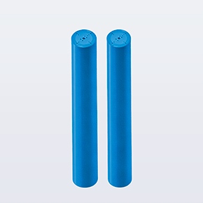
Heavy-duty forged cylinder construction with micro-honed internal bores and specialized low-friction subsea seal packages. Engineered for high-flow discharge duty with ASME Section VIII and EU PED design code review per project specification.
Consolidates quarter-turn isolation, controlled manual depressurization, and safety relief over-pressure protection into a single manifold block supporting ISO 4413 system safety principles.
High-flow CNC manifold blocks providing streamlined fluid distribution between multiple accumulator bottles, pilot lines, and ROV interface connections with minimized pressure drop.
18. Offshore Jurisdiction & Regulations: U.S. OCS (BSEE 30 CFR 250.734), North Sea, or local authority
19. Design Codes & Inspection Scope: ASME Section VIII, EU PED, 3.1 MTR, Factory Acceptance Test (FAT) protocol
Request Subsea Hydraulic Engineering Review
Submit your BOP stack model, target actuator stroke volumes, operating water depth, and ROV interface specifications for a comprehensive sizing dossier.
❓ Frequently Asked Engineering Questions
In subsea BOP installations, an accumulator bank provides stored, pressurized hydraulic fluid located directly on the subsea stack or ROV intervention skid. When an ROV connects via hot stab or actuates intervention valves, the stored hydraulic reserve is available locally without requiring pump ramp-up or relying on real-time fluid pumped from the surface through long, high-resistance umbilicals to stroke rams or release locks.
No. BOP wellbore pressure ratings (such as 15,000 psi or 20,000 psi) describe the pressure-containing capability of the BOP forgings, wellhead, and ram blocks against subterranean reservoir fluids. In contrast, the hydraulic accumulator control circuit operates at hydraulic fluid power pressures (often around 3,000 psi, with project-specific ratings configured per OEM actuator specification) designed to power the BOP hydraulic operating cylinders.
Accumulator capacity is sized based on the exact stroke volume of targeted BOP actuators, accounting for the pressure drawdown from precharge pressure (P₀) to minimum operating cut-off pressure (P₂). Sizing must follow applicable control-system methodologies (such as API Spec 16D criteria), incorporating polytropic gas expansion coefficients, deepwater ambient hydrostatic pressure, seabed operating temperatures, and real-gas compressibility factors where required.
No. ROV intervention is an independent secondary intervention capability and does not replace required primary or automatic emergency control functions. Automated emergency systems such as autoshear, deadman, and Emergency Disconnect Sequences (EDS) are mandated under 30 CFR 250.734(a)(6) to actuate autonomously upon uncommanded riser disconnect or complete loss of control communications. ROV intervention provides auxiliary secondary actuation and operational support.
For U.S. OCS operations, BSEE incorporates API Standard 53 (Fifth Edition, December 2018) into 30 CFR Part 250, governing well-control equipment systems and establishing critical response times for ram closure, locks, and ROV intervention functions. API Recommended Practice 17H (Second Edition, June 2013; Errata January 2014) standardizes subsea ROV intervention tooling, hot-stab profiles, and receptacle dimensions. BOP and LMRP ROV panels must conform to API RP 17H, and SCHWERLL coordinates manifold hydraulic connections to match the project-approved interface drawings.
Yes. Ambient seawater hydrostatic pressure increases at approximately 0.1 bar per meter of water depth (~300 bar at 3,000 m). Deepwater accumulator sizing must consider the actual pressure reference used by the accumulator design (surface-referenced vs. ambient-compensated), ambient hydrostatic pressure, deployment depth, seabed temperature, and the OEM control-system architecture to ensure adequate usable fluid volume is delivered at the actuator.
To initiate engineering review, please submit: 1) BOP OEM and stack model; 2) Target intervention functions (open and close shear rams, pipe rams, locks, LMRP unlatch); 3) Required actuator fluid stroke volumes and function response times; 4) Hydraulic operating and minimum cut-off pressures; 5) Maximum water depth and ambient temperature; 6) Hydraulic fluid specification; 7) Available mounting envelope and submerged weight budget; and 8) Applicable design codes (ASME Section VIII, EU PED) and inspection documentation scope.
Need Subsea BOP Intervention Sizing or Skid Integration?
Our offshore engineering division provides thermodynamic gas sizing, API 53/17H interface review, and formal technical dossiers.
Servo hydraulic cylinder with a piston rod displacement sensor: To implement closed-loop control of hydraulic systems—such as flow‑rate regulation—it is essential...
Hydroelectric generating units harness the potential energy of flowing water in a hydromechanical system, characterized by constantly varying flow velocity and discharge,...
🍪 Cookie & Analytics Notice: We use essential cookies to operate our site and optional analytics to measure accumulator sizing calculator usage and improve fluid engineering services. You can adjust your choice at any time. Learn more in our Privacy Policy.