In conventional step‑type heating furnace hydraulic system design, flow is supplied by several constant‑pressure variable‑displacement pumps. Due to load imbalances, the system’s power rating must be sized to accommodate the peak demand during the lifting phase of the stepping beam. Consequently, the drawbacks of such conventional systems are quite pronounced: high installed power; complete conversion of the stepping beam’s gravitational potential energy into heat during descent, leading to excessive hydraulic system temperatures that can only be managed by increasing the cooling capacity of the cooler; and a larger overall footprint, as the greater number of pumps necessitates a correspondingly larger oil tank and auxiliary components, resulting in higher capital costs and increased energy consumption.
In light of the operating conditions, such as the cycle time of the walking beam, an accumulator system is employed to replace the oil pump‑motor unit as the primary power source for lifting and other motions of the heating furnace’s walking beam, upgrading the system to include… An energy-saving hydraulically controlled system with potential energy recovery functionality, It can significantly reduce the system’s installed capacity and enable recovery of potential energy during the descent phase. Meanwhile, by appropriately upgrading and modifying components such as the hydraulically controlled valve group, hydraulic balance in the step‑type furnace’s hydraulic control system is achieved, providing a stable balancing force for the furnace’s stepping beam and compensating for the combined weight of the beam and the steel billets. This not only substantially lowers the hydraulic system’s installed power but also ensures more balanced system operation.
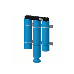
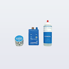
The key technical aspects of upgrading the potential‑energy recovery and energy‑saving system for a step‑type reheating furnace involve replacing the conventional multi‑unit oil‑pump motor drive with an accumulator‑based power source. The reliability of the primary power source is critical to the long‑term stable operation of the step‑type reheating furnace; ensuring its sustained, dependable performance hinges on maintaining stable, reliable monitoring of the power source’s energy levels, thereby keeping the energy required for its operation under control. , The key to the hardware configuration of this type of energy‑saving system lies in reliably monitoring the liquid level of the compressed gas stored in the accumulator system, which serves as the primary power source for the energy‑saving system. Through market research, SCHWERLL It features a mature and reliable on-site display and analog signal output device for monitoring the accumulator’s piston position. This system enables dependable energy‑level monitoring of the accumulator’s primary power source in energy‑saving potential‑energy recovery systems and has been steadily deployed across various industrial sectors, including numerous large‑scale key projects both internationally and domestically. The salient characteristics of this energy‑monitoring system are:
- The monitoring system is installed on the pressurized nitrogen side, featuring a compact mounting structure and independent installation.
- The monitoring system can provide reliable limit and controlled-position signals for the upper and lower extreme positions of the energy-storage power source system.
- The monitoring system can accurately provide 4-20mA Continuous output of liquid level signal
- The monitoring system provides an on-site visual monitoring display panel and, in conjunction with signal outputs, enables control of the system’s critical margins. Request