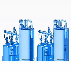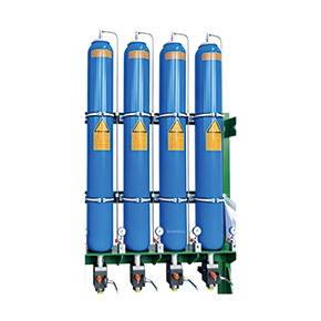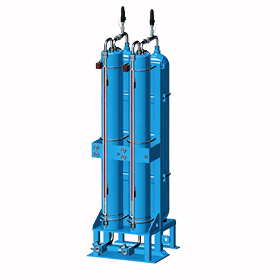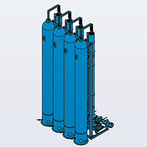
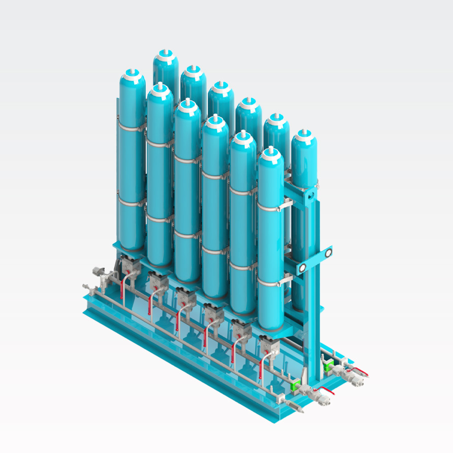
SCHWERLL designs and supplies standard bladder-type accumulator systems engineered for centralized hydraulic energy storage, rapid emergency discharge, pulsation damping, and high-flow circuit stabilization in heavy industrial installations. By integrating multiple standard bladder accumulator vessels (BAK, BAKM, and BAKH series) into project-engineered rack or skid assemblies with fluid distribution manifolds (configuration depends on project design) and integrated safety shut-off blocks, SCHWERLL delivers accumulator power stations matched to project hydraulic and regulatory specifications.
ud83dudccb System Specifications & Integration Parameters
| System Configuration | Multi-vessel rack or modular skid assembly with project-specific fluid manifold; centralized gas charging / monitoring manifold available where required. |
| Compatible Accumulator Units | SCHWERLL BAK (standard industrial), BAKM (high-flow), and BAKH (large-volume) bladder accumulators (individual vessel pressure and volume ratings detailed on the Standard Bladder Accumulator page) |
| Total Stored Energy Capacity | Total installed accumulator volume is engineered from required usable fluid volume, operating pressure envelope, duty cycle, redundancy, installation footprint and selected vessel configuration. |
| Design Working Pressure | System allowable working pressure is governed by the lowest-rated component in the assembled pressure circuit and must be confirmed from the approved system configuration, manifold, valve, piping and vessel ratings. |
| Safety & Isolation Integration | Integrated SCHWERLL safety and shut-off valve blocks (AJS Series — commercial / internal series designation) providing circuit isolation, over-pressure protection, controlled depressurization, and test interfaces aligned with ISO 4413; specific accessory configuration confirmed per project P&ID |
| Standards & Regulatory Scope | Configured according to applicable hydraulic-system, pressure-vessel and regional regulatory requirements defined for the project (such as GB/T 20663-2026, TSG 21-2016, EN 14359, EU PED 2014/68/EU, or ASME Section VIII design criteria) |
| Inspection & Quality Scope | Inspection and functional testing scope is defined by the supplied configuration, applicable component standards and approved project ITP/FAT plan. |
| Hydraulic Fluid Compatibility | Fluid compatibility depends on the selected accumulator elastomer, valve seals, hose/manifold materials and complete system component specification. |
| System RFQ Information | Required effective fluid discharge (ΔV), operating pressure envelope (P_1, P_2), discharge cycle time, fluid medium, solenoid voltage, and installation footprint limits |
Core System Sub-Assemblies & Engineering Integration
The construction of a standardized bladder accumulator system integrates essential safety, control, and structural components to ensure safe operation, code compliance, and ease of plant maintenance:
- Structural Accumulator Rack: Structural rack or skid arrangement is engineered to project requirements. Vessel orientation, support structure and mounting hardware are defined by the approved project GA drawing, vessel quantity, installation space, transport requirements and structural specification.
- High-Pressure Fluid Header: Fluid-side distribution manifold material, bore size, connection type and allowable pressure are selected according to the required flow, pressure and project piping specification, complete with drain points and system interfaces.
- Accumulator Safety & Shut-Off Valve Block: In accordance with fluid power safety practices (such as ISO 4413), the required isolation, over-pressure protection, depressurization, test and pressure-monitoring functions are defined from the applicable hydraulic-system safety requirements and project P&ID:
- Fluid isolation valve (manual ball valve with optional padlockable lockout device);
- Over-pressure protection device selected to project pressure and regulatory requirements;
- Test interface for system diagnostic sensors and pressure verification;
- Controlled manual or solenoid-actuated pressure relief path to reservoir;
- Pressure gauge or electronic pressure transmitter connection marked with allowable working pressure.
- Centralized Nitrogen Manifold — Optional: Interconnecting gas lines linking individual bladder gas valves to a common filling, testing, and pressure monitoring station, streamlining precharge servicing where specified by the project configuration.
Codes, Standards & Regulatory Review Alignment
The construction and supply of bladder-type accumulator systems must comply with the applicable codes and standards of the country or region where the equipment is installed and operated:
- Engineering Standards Alignment: The integrated accumulator system is configured according to the applicable hydraulic-system, pressure-vessel and regional regulatory requirements defined for the project. Technical references include China national standard GB/T 20663-2026, Special Equipment Safety Regulation TSG 21-2016, and European standard EN 14359 for gas-loaded accumulators.
- Regional Regulatory Review Scope: Regional regulatory review may include EU PED (Directive 2014/68/EU), ASME Section VIII design requirements, China pressure-equipment regulations, Brazil NR-13, Eurasian TR CU requirements, or Australia AS 1210 depending on destination country and project configuration.
- Pressure Piping Scope: Where connecting gas or fluid headers fall within applicable local pressure-piping regulatory scope, piping design, materials, inspection and documentation must follow the governing regional requirements.
System Applications & Component Interconnect
Typical application sectors include heavy metallurgy, die-casting, hydraulic presses, marine hydraulic systems and emergency hydraulic energy-storage duties:
- Component Vessel Selection: For standalone vessel parameters and replacement elastomer bladders, review our Standard Bladder Accumulator component specifications.
- Safety Manifold Hardware: For available isolation, depressurization, monitoring and actuation configurations, review the Accumulator Safety & Shut-Off Valve Block page; final porting, relief setting and actuation configuration are confirmed per model/project.
- Piston Alternative Systems: Piston accumulator systems may be considered where project requirements favor larger usable volume, position monitoring, packaging geometry, pressure ratio or other duty-specific characteristics. Final accumulator technology is selected by engineering review. Consult our High-Pressure Piston Accumulator engineering team for technical comparison.
- Preliminary Volumetric Estimates: For initial energy storage and isothermal/adiabatic volume calculations, access the Hydraulic Accumulator Sizing Calculator.