A hydraulic accumulator operating mechanism stores pressurized hydraulic energy so that a high-voltage circuit breaker can execute required high-speed opening, closing, and rapid autoreclosing duty cycles without relying on instantaneous hydraulic pump delivery. By coupling pre-charged nitrogen gas with fluid energy storage, the accumulator bank delivers rapidly available stored hydraulic energy directly to the operating cylinder while maintaining an autonomous reserve to drive emergency tripping operations during auxiliary substation power interruptions.
SCHWERLL engineers dedicated hydraulic accumulator energy storage subsystems, integrated safety shut-off manifolds, and electronic pressure monitoring modules tailored for high-voltage circuit breaker mechanisms. Note: Exact stored energy, operating pressure envelope, and sequence duty are strictly governed by the circuit-breaker OEM mechanism design. SCHWERLL supplies the hydraulic power and energy storage subsystem; the complete circuit breaker, interrupting chamber, and kinematic linkages are supplied by the switchgear OEM.
1. High-Voltage Circuit Breaker Subsystem Responsibility Boundary
To ensure precise technical integration and prevent scope ambiguity during substation engineering procurement, the boundary between the SCHWERLL hydraulic energy subsystem and the circuit-breaker OEM assembly is defined below:
| System Component |
Functional Role in Operating Mechanism |
SCHWERLL Engineering Scope |
Circuit Breaker OEM Scope |
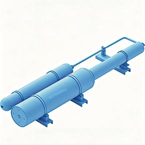
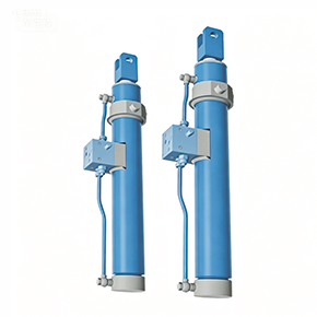
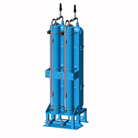
| Hydraulic Accumulator |
Stored hydraulic operating energy; nitrogen precharge pressure maintenance for rapid contact actuation |
SCHWERLL supply & sizing scope (Piston / Bladder) |
Cabinet mounting bracket & interface porting |
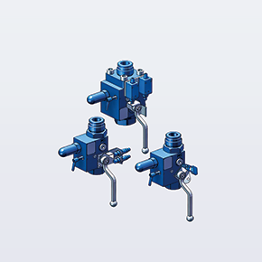
| Hydraulic Safety Manifold |
Circuit isolation, over-pressure safety relief, manual depressurization to tank, and check-valve protection |
SCHWERLL supply & engineering scope (AJS Valve Block) |
Pilot valve integration & mechanism line routing |
| Pressure Monitoring |
Continuous hydraulic pressure sensing, gauge ports, and threshold signaling for pump start/stop and trip lockout |
SCHWERLL supply & integration scope where specified |
Relay trip logic & substation SCADA interlocks |
| Operating Cylinder / Actuator |
High-speed hydraulic driving cylinder coupled to the circuit breaker mechanical interrupters |
OEM interface definition (Fluid delivery matching) |
Breaker OEM design, manufacture & kinematic coupling |
| Breaker Kinematic Linkage |
Mechanical drive rods, latching mechanisms, position indicators, and anti-pumping mechanical linkages |
Not in scope (Kinematic interface only) |
Breaker OEM scope |
| Interrupting Chamber / GIS |
SF6 or vacuum arc-extinction chambers, high-voltage bushings, current paths, and gas insulation enclosure |
Not in scope |
Breaker OEM / Switchgear manufacturer scope |
| Substation Protection Relays |
Protective relaying, trip/close command initiation, trip coil actuation, and substation supervisory control |
Not in scope |
Substation EPC / Protection engineering scope |
2. Operating Duty Cycles & Standards Alignment (IEC 62271-100 & IEC 62271-1)
In electric transmission and distribution substations, high-voltage alternating-current circuit breakers (including live-tank, dead-tank, and Gas-Insulated Switchgear – GIS) must comply with operating sequences and service conditions defined by switchgear standards, notably IEC 62271-100:2021 + AMD1:2024 (High-voltage switchgear and controlgear — Part 100: Alternating-current circuit-breakers) and IEC 62271-1:2017 + AMD1:2021 (Common specifications).
The hydraulic operating subsystem must be engineered to deliver sufficient fluid energy for rated operating sequences specified by the switchgear OEM, such as:
- O – 0.3 s – CO – 3 min – CO: Example rated operating sequence where specified by the breaker OEM, consisting of a trip operation followed by rapid autoreclosing after 0.3 seconds, with intermediate recharge intervals.
- CO – 15 s – CO: Example alternative operating sequence where specified by the breaker manufacturer.
- Autonomous Stored Energy Reserve: If auxiliary substation AC power is temporarily interrupted, stored hydraulic energy in the accumulator bank ensures locally available fluid pressure to execute required opening (trip) operations without motorized pump delivery.
Environmental Service Conditions: IEC 62271-1 defines normal outdoor service conditions with ambient air temperatures from +40°C down to -25°C. Projects outside normal service conditions, including lower-temperature or higher-temperature substations, require project-specific environmental review. SCHWERLL performs nitrogen precharge pressure (p₀) temperature compensation and seal elastomer selection for special service conditions where specified.
Engineering Governance Notice: Applicable pressure-vessel design, regulatory and documentation requirements are reviewed per project specification (such as ASME Section VIII, EU PED 2014/68/EU, or TSG 21). IEC 62271-100 specifies total circuit breaker apparatus performance; SCHWERLL accumulator subsystems are engineered to meet the operating-duty requirements defined by the breaker OEM rather than standalone apparatus certification. Inspection and documentation scope, including hydrostatic proof testing and EN 10204 3.1 material documentation, are available where specified by the product configuration and purchase order.
3. Accumulator Sizing Inputs for Breaker Mechanism Review
Operating pressure varies substantially by breaker design and operating mechanism; use the OEM-specified maximum and minimum actuation pressures for accumulator sizing. Volumetric sizing of the hydraulic energy bank is conducted using real-gas polytropic equations (p · Vn = const, where n ≈ 1.3–1.4 for rapid adiabatic discharge). The following parameters are required to configure an accumulator subsystem:
1. Maximum Operating Pressure (p₂)
OEM-specified maximum hydraulic operating pressure.
2. Minimum Operating Pressure (p₁)
OEM-specified lowest allowable actuation pressure before the breaker mechanism signals low-pressure trip lockout.
3. Fluid Volume per Opening Stroke (ΔV_open)
Net displaced oil volume required by the operating cylinder during high-speed opening.
4. Fluid Volume per Closing Stroke (ΔV_close)
Displaced oil volume required to compress main contact springs and latch the breaker closed.
5. Specified Operating Sequence
Required duty sequence (e.g. O-0.3s-CO, CO, or custom multi-cycle autoreclose) without intermediate pump recharge.
6. Minimum Residual Pressure Envelope
Pressure remaining after the completion of the full duty sequence, ensuring safe latching margins.
7. Pump Recharge Time (t_recharge)
Time allotted for the motorized hydraulic pump to restore system pressure from p₁ back to p₂.
8. Ambient Temperature Envelope
Outdoor substation service conditions (normal outdoor service +40°C to -25°C per IEC 62271-1, or project-specific special service conditions), governing nitrogen gas pre-charge p₀ compensation.
9. Hydraulic Fluid Specification
Low-pour-point aviation hydraulic fluid, synthetic ester, or mineral oil (ISO VG 15/32/46).
10. Installation Envelope & Orientation
Mechanism cabinet space dimensions, vertical mounting preference, or horizontal layout requirements.
11. Position Monitoring Requirements
Optional linear displacement transducers or ultrasonic piston switches for remote digital stroke monitoring.
12. Pressure Vessel Design Codes
Applicable regulatory jurisdiction: ASME Section VIII Div. 1, European PED 2014/68/EU, or Chinese TSG 21.
Engineers can perform preliminary gas sizing via the SCHWERLL Sizing Calculator before submitting finalized breaker OEM kinematic profiles for engineering review.
4. Accumulator Technology Comparison: Piston vs. Bladder in Switchgear Service
Both piston accumulators and bladder accumulators are widely deployed across high-voltage circuit breaker mechanisms. Selection depends on spatial packaging, required displacement volume, and maintenance philosophy:
- Flexible Usable Volume: Readily engineered in long, slim cylindrical aspect ratios to maximize usable volume within narrow switchgear mechanism cabinets.
- Position Feedback: Internal piston position can be monitored continuously using external ultrasonic sensors or magnetic linear encoders to verify stored oil volume remotely.
- Gas/Oil Separation: Solid metallic piston with engineered elastomeric/PTFE seal packages prevents rapid gas permeation over multi-year substation standby.
- Custom Packaging: Manifold blocks and safety shut-off valves can be integrated directly onto the accumulator fluid cap.
⚡ Bladder Accumulators (BAK Series)
- Low Moving Mass: Rapid fluid delivery due to the low inertia of the flexible elastomeric bladder, matching high-speed pilot valve response.
- Compact Installation: Ideal for smaller distribution switchgear and modular medium-to-high voltage reclosers requiring lower fluid displacement.
- Mechanical Simplicity: No sliding internal friction surfaces; reliable performance across standard temperature ratings.
- Precharge Maintenance: Requires periodic precharge verification using portable nitrogen charging kits per accumulator charging SOPs.
5. Emergency Operation Procedures
In high-voltage circuit breakers equipped with stored-energy hydraulic operating mechanisms, when an emergency condition occurs—such as a complete loss of substation auxiliary control power or an electric motor energy storage failure—an emergency trip or closing operation may be executed manually. Safety protocols must be rigorously adhered to, releasing hydraulic fluid through the dedicated manual emergency valve:
- Confirm Status: Inspect the accumulator pressure gauge and monitoring instruments to verify that the hydraulic oil pressure is within the rated operating range, confirming sufficient stored energy is available for actuation.
- Isolate Power Supply: Disconnect the electrical control power supply and the hydraulic motor pump power circuit to prevent accidental pump restart or unintended electrical actuation during manual intervention.
- Open Manual Unloading / Emergency Valve: Slowly and deliberately actuate the manual emergency mechanical valve on the hydraulic mechanism (or safety manifold) to direct high-pressure hydraulic fluid from the accumulator directly into the main operating cylinder.
- Supervisory Verification: Observe the circuit breaker’s mechanical position indicator to visually verify that the interrupter contacts have reached their fully open (tripped) or fully closed position.
- Close the Valve: Immediately after the mechanical motion is completed, close the manual emergency valve or handle to maintain hydraulic system isolation and prevent continuous fluid bypass to the reservoir.
6. Safety Precautions
- High-Pressure Nitrogen Hazard: High-pressure piston and bladder accumulators contain pre-charged nitrogen gas (typically on the order of tens of megapascals). Operating personnel are strictly prohibited from loosening, tightening, or tampering with the gas inflation valve plug while the vessel is pressurized.
- Authorized Operational Personnel: Non-professional substation on-duty personnel shall not perform mechanical emergency operations without authorization; all manual operations must be conducted using certified insulating operating tools, dedicated handles, and approved personal protective equipment (PPE).
- Post-Emergency Comprehensive Inspection: Following any manual emergency operation, the hydraulic system must undergo thorough diagnostics (inspecting auxiliary electrical supply, oil pump motor, pressure switches, microswitches, and oil cleanliness) before restoring the breaker to automated service.
7. Engineering RFQ Specification Checklist
To receive a formal engineering review and customized sizing proposal for high-voltage circuit breaker accumulator mechanisms, provide the following parameters with your inquiry:
- Circuit breaker OEM & model designation
- Rated voltage class (kV) & interrupting medium (SF6 / GIS / Vacuum)
- Operating mechanism type & manufacturer
- Required opening hydraulic displacement (liters)
- Required closing hydraulic displacement (liters)
- Required duty cycle sequence (e.g. O-0.3s-CO)
- Maximum working hydraulic pressure & minimum actuation threshold (defined by breaker OEM)
- Pump recharge time requirement (seconds)
- Hydraulic fluid specification (ISO VG / aviation oil)
- Minimum / Maximum Ambient Temperature at Installation Site
- Cabinet installation envelope dimensions (H × W × D)
- Accumulator mounting orientation (vertical / horizontal)
- Electronic position / pressure monitoring requirements
- Required redundancy (dual accumulator bank / isolation blocks)
- Pressure vessel design codes (ASME VIII / PED / TSG 21)
- Required inspection dossiers (e.g. hydrostatic proof testing, EN 10204 3.1 material documentation where specified)
- Target project quantity & commissioning destination