1. System Identity & Operational Requirement
Offshore platforms experience oscillations due to wind, waves, and other marine environmental factors. Similarly, during operations such as jacking systems, offshore wind-energy installations, ships, and the stabilization of large industrial equipment, uneven external forces, non-uniform load resistance, or mechanical transmission accuracy differences can all necessitate rapid, coordinated leveling adjustments.
SCHWERLL’s Accumulator-Powered Hydraulic Leveling System provides an engineered fluid-power solution for dynamic structural leveling. By employing hydraulic accumulators to buffer dynamic energy, absorb hydraulic shocks, and rapidly release stored fluid, circuit pressure fluctuations across multi-cylinder configurations are balanced. Integrated real-time servo flow response feedback continuously modulates fluid delivery, enabling stable and high-precision leveling performance under shifting external disturbance.
2. Published Leveling Control Principle
In accordance with SCHWERLL’s published leveling solution architecture, dynamic leveling and structural stabilization operate through a coordinated 5-stage functional sequence:
Stage 1: External Disturbance & Uneven Load Dynamics
Environmental excitation (wind, ocean waves) or operational factors (jacking friction, non-uniform ground support, mechanical transmission differences) induce angular tilt and dynamic load shifts across the supported structure.
Stage 2: Accumulator Dynamic Energy Buffering
An accumulator-based power unit buffers, absorbs, and releases hydraulic energy, supplying instantaneous fluid volume during rapid leveling demands without relying solely on continuous primary pump flow.
Stage 3: Pressure-Fluctuation Balancing
Accumulator energy storage dynamically mitigates circuit pressure spikes and balances pressure differences across multiple hydraulic leveling cylinders, preventing circuit cavitation or structural shock.
Stage 4: Real-Time Servo Flow Feedback
Real-time servo flow response feedback is used to support dynamic hydraulic leveling and high-precision leveling performance across hydraulic actuators.
Stage 5: High-Precision Leveling Delivery
Coordinated hydraulic regulation delivers steady, high-precision leveling performance across structural support points throughout the operation.
3. Leveling Mechanisms & Configuration Flexibility
Every hydraulic leveling installation is engineered to match the mechanical structure and disturbance environment of the application:
Operational Mechanism Options
Published leveling modes: active, passive, or combined active/passive arrangements. Final control implementation is project-specific.
Vessel Selection Context: When the load requiring leveling is substantial, an accumulator-based power unit is typically utilized. SCHWERLL’s published leveling solution notes that piston-type accumulators are generally selected where higher system reliability is required. SCHWERLL’s published solution also describes configurations using multiple standby fixed pressure vessels alongside accumulators where appropriate to the project, published as a cost-oriented configuration approach. Final vessel selection and circuit configuration are determined by project engineering.
Sizing & Distribution Engineering: The required volume, operating pressure envelope, and physical distribution of accumulators within the leveling circuit are calculated from specific operating conditions: supported static load, dynamic wave or motion spectra, actuator cylinder dimensions, required cycle frequency, and allowable pressure drop.
4. Related Engineering Components & System Options
Component selection depends on project load, dynamic disturbance profile, required stroke, fluid media, and circuit architecture. The products below are related engineering options, not a fixed standard bill of materials.
Depending on application scope, SCHWERLL configures the leveling system utilizing relevant fluid power components:
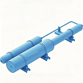
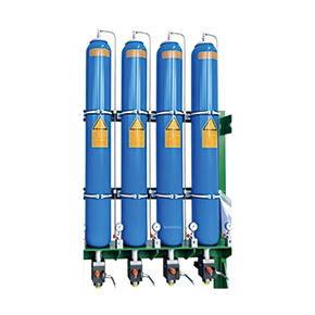
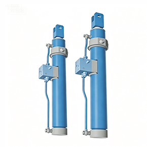
- Piston Accumulator: Piston-type accumulator configurations may be evaluated where the project requires substantial load support or higher reliability. Final product family is selected by project engineering.
- Piston Displacement Energy Monitoring Systems: Monitoring options may be reviewed where required by project architecture.
- Accumulator Safety & Shut-Off Valve Blocks: Safety and isolation manifold options may be reviewed where required by project architecture.
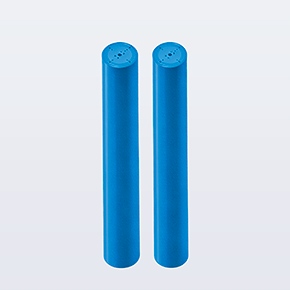
- Standby Fixed Pressure Vessels: Multiple sets of standby fixed pressure vessels may be configured alongside accumulators as a published cost-oriented approach where large fluid energy reserves are specified.
All component selections are modular options confirmed in the agreed project bill of materials (BOM), rather than fixed off-the-shelf standard assemblies.
5. Quality Assurance, Pressure Codes & Documentation
SCHWERLL operates under an ISO 9001:2015 corporate quality management system.
Applicable pressure-equipment design-code, conformity-assessment and project documentation requirements are reviewed according to the approved component configuration, pressure-bearing equipment scope, destination market and project specification. Where pressure-bearing vessels or piping assemblies are included, example project design and conformity assessment frameworks (such as ASME Boiler and Pressure Vessel Code Section VIII or European Pressure Equipment Directive 2014/68/EU) may be evaluated according to the specified scope of supply.
6. Direct Technical Inquiry & RFQ Submission Guidelines
Because every leveling installation is tailored to specific structural geometries, motion degrees of freedom, and load profiles, SCHWERLL does not offer generic fixed-lead-time leveling packages. To initiate an engineering review and preliminary sizing evaluation, please provide the following technical parameters:
- Supported Structure / Equipment Type: Offshore platform, jacking system, wind-turbine installation, ship / marine leveling application, or heavy industrial machinery.
- Leveling Architecture & Points: Number of leveling points, actuator cylinder dimensions (bore/rod/stroke), and spatial layout.
- Load & Motion Profile: Static load per support point, dynamic load variance, required leveling stroke, and target leveling accuracy tolerance.
- Disturbance Spectrum: Wave height/period, wind speed, jacking speed, or external disturbance frequency.
- Hydraulic Power Conditions: Available primary pump supply flow (L/min), system operating pressure, and recharge intervals.
- Operating Media & Environment: Hydraulic fluid designation, ambient temperature envelope, and marine/corrosion protection requirements.
- Control & Interface Scope: Preferred control PLC / communication bus, servo valve interface, and feedback instrumentation scope.
- Regulatory & Inspection Requirements: Destination market, applicable pressure equipment codes, and required documentation dossiers.
Commercial & Documentation Notice: Lead time is confirmed after leveling architecture, hydraulic requirements, control scope, documentation and quantity are defined. Project-specific drawings, control documentation, inspection requirements and supplied documentation are defined in the agreed project scope. Preliminary sizing calculations evaluate gas-side polytropic thermodynamic behavior for stored energy sizing. Sizing of leveling cylinders, servo valves, and overall leveling accuracy requires formal project engineering review.