Constant-Flow Energy Storage Power Source Test System
SCHWERLL accumulator-based constant-flow test system uses energy-storage feedback, flow measurement and servo flow control to provide stable flow output for test loads.
⚡ Hydraulic Supply:Large Instantaneous Flow
🎯 Control Architecture:Flow-Servo Reference
🔄 Feedback Signals:Liquid-Level & Flow Signal
📦 System Scope:Engineered per Test Load
📐 Hydraulic Circuit Architecture & System Integration
Constant-Flow Architecture
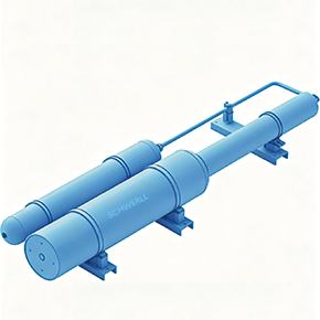
Accumulator energy storage bank, liquid-level feedback instrumentation, discharge-line flow measurement, and flow-servo control architecture (Illustrative system architecture — configuration engineered per test load requirements).
Operational Focus & Value Proposition:
Engineered to supply large instantaneous hydraulic flow from accumulator energy storage and deliver stable, high-precision steady-state flow to test loads through liquid-level feedback, fluid-mechanics compensation, and closed-loop flow-servo control.
1. System Identity & Operational Requirement
In high-demand fluid power testing and dynamic load validation, conventional hydraulic pumping systems often struggle to satisfy abrupt flow variations without severe pressure drop or oversized motor installations. When the test object or load requires a constant flow rate during transient operating cycles, an accumulator energy-storage installation capable of providing large instantaneous hydraulic flow is employed, with its transient output flow precisely controlled.
SCHWERLL’s Constant-Flow Energy Storage Power Source Test System bridges the gap between instantaneous stored hydraulic energy and tight steady-state delivery requirements. Rather than treating the accumulator bank merely as an unmanaged pressure reservoir, the solution integrates internal fluid state tracking, discharge pipeline flow measurement, and high-frequency servo regulation to supply constant flow to the test object under changing downstream impedance.
2. Published Constant-Flow Control Architecture
In accordance with SCHWERLL’s published solution architecture, the power source achieves high-precision steady-state delivery through a 6-stage functional sequence:
Stage 1: Dynamic Energy Storage & Instantaneous Fluid Delivery
An engineered hydraulic accumulator installation provides the large instantaneous fluid volume and peak power required during transient test cycles, eliminating the need to oversize the primary electric motor and hydraulic pump package.
Stage 2: Liquid-Level Feedback
Liquid-level information is collected from the energy-storage system to monitor available fluid reserves throughout test operation.
Liquid-level feedback is used in fluid-mechanics compensation calculations to derive instantaneous flow data from the energy storage subsystem.
Stage 4: Discharge Pipeline Flow Feedback
Discharge-line flow signals are collected from the fluid delivery pipeline leading to the test load.
Stage 5: Reference Comparison & Error Generation
The calculated flow data is compared with the measured discharge-line flow signal to generate a stable, accurate control reference for closed-loop modulation.
The overall flow-servo control system modulates fluid output based on the reference signal, delivering high-precision constant-flow performance to the test object throughout the test cycle.
Where displacement-based estimation is used, hydraulic flow can in principle be derived from measured displacement and velocity together with known effective internal geometry. By taking the time derivative of piston or liquid-column displacement ($Q = A cdot frac{dx}{dt}$), instantaneous flow rates can be estimated independently from downstream pressure pulsations.
Engineering Disclaimer: This kinematic relationship represents general fluid power engineering principles. It is provided for technical clarity and is not a certified measurement method, proprietary SCHWERLL algorithm claim, nor necessarily the measurement architecture of every supplied system. Actual calculation algorithms and measurement architectures are project- and configuration-specific.
Measurement Instrumentation Boundary: Liquid-level sensing and discharge-line flow measurement methods are selected according to operating pressure, fluid media, dynamic response requirements, and environmental conditions. Specific transducer technologies and pipeline flowmeters are determined during project engineering review.
4. Related Engineering Components & System Options
Component selection depends on project pressure, required flow, stored-energy demand and circuit architecture. The products below are related engineering options, not a fixed standard bill of materials.
Depending on application scope, SCHWERLL configures the system utilizing relevant fluid power components:
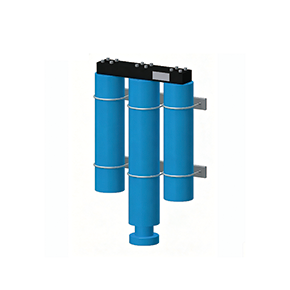
High-Pressure Piston Accumulators: Sized for large usable volume, extended stroke length, and high-parameter stored energy capacity to sustain extended constant-flow runs.
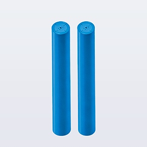
Standard Bladder Accumulators: Integrated for fast-response transient peak support, pulsation attenuation, and localized pilot pressure stability.
Accumulator Safety & Shut-Off Valve Blocks: Providing overpressure relief, manual or solenoid-operated fluid isolation, and emergency circuit depressurization in alignment with ISO 4413 requirements.
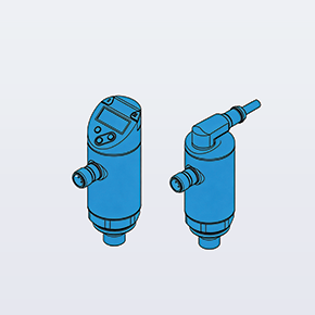
Liquid-Side High-Pressure Manifolds: Precision-machined fluid distribution manifolds integrating measurement ports, isolation valves, and direct servo-valve mounting interfaces.
All component selections are modular options confirmed in the agreed project bill of materials (BOM), rather than fixed off-the-shelf standard assemblies.
SCHWERLL operates under an ISO 9001:2015 corporate quality management system.
Applicable pressure-equipment design-code, conformity-assessment and project documentation requirements are reviewed according to the approved system configuration, pressure-bearing equipment scope, destination market and project specification. Where pressure-bearing vessels or piping assemblies are included, example project design and conformity assessment frameworks (such as ASME Boiler and Pressure Vessel Code Section VIII or European Pressure Equipment Directive 2014/68/EU) may be evaluated according to the specified scope of supply.
6. Direct Technical Inquiry & RFQ Submission Guidelines
Because every constant-flow power source test system is tailored to specific test load profiles, SCHWERLL does not offer generic fixed-lead-time test bench packages. To initiate an engineering review and preliminary sizing evaluation, please provide the following technical parameters:
Commercial & Documentation Notice: Project-specific drawings, control documentation, inspection requirements and supplied documentation are defined in the agreed project scope. Preliminary sizing calculations using the SCHWERLL sizing tool evaluate gas-side polytropic thermodynamic behavior for stored energy sizing. Sizing of flow-servo control elements, servo valves, and overall test system accuracy requires formal project engineering review. Final lead times and documentation deliverables are confirmed upon completion of technical review.
❓ Frequently Asked Engineering Questions
A constant-flow accumulator energy-storage test system is an engineered hydraulic power-source solution designed for testing applications where the test object or load demands a constant flow rate. Instead of relying solely on continuous pump delivery to meet sudden flow requirements, the system employs an energy-storage accumulator installation capable of providing large instantaneous flow, while actively controlling transient output flow to maintain stable delivery.
The system utilizes accumulator energy storage to deliver the required fluid volume and peak instantaneous flow. By monitoring liquid-level information within the energy-storage system and executing fluid-mechanics compensation calculations, the control system derives instantaneous flow data and compares it with measured flow signals acquired from the discharge pipeline. This comparison generates a stable, accurate reference signal that drives the SCHWERLL flow-servo control system to deliver high-precision constant-flow output to the test load.
The control architecture utilizes two primary feedback signals: liquid-level information gathered from the energy-storage accumulator system, and discharge-line flow measurement from the fluid outlet pipeline. The physical sensing technology (such as linear position sensing, external level transmitters, or calibrated pipeline flowmeters) is selected according to project operating pressure, fluid media, dynamic response requirements, and environmental conditions.
System pressure, accumulator capacity, and target flow are project-specific engineering determinations. They are calculated based on the test load's operating envelope, required steady-state flow rate, peak instantaneous demand, permissible pressure variance, duty cycle duration, and available hydraulic recharge capacity. No fixed standard ratings apply across all applications.
No. SCHWERLL configures the energy-storage power source test system using accumulator technologies and instrumentation appropriate for the application parameters. Piston accumulators, bladder accumulators, or multi-vessel accumulator racks may be integrated depending on required usable volume, fluid compatibility, and pressure requirements. Instrumentation and monitoring hardware are selected per approved project specifications.
Engineering review requires defining the target constant flow range, allowable flow variation/tolerance, working pressure envelope, load profile and duty cycle, hydraulic fluid type and operating temperature range, available primary power or pump supply, control interface preferences, and applicable documentation or pressure-equipment design-code requirements.
Need Constant-Flow Test System or Hydraulic Power Source Sizing?
Our fluid power engineering team reviews test-load flow requirements, system operating pressure, accumulator capacity, and servo control interfaces.
🍪 Cookie & Analytics Notice: We use essential cookies to operate our site and optional analytics to measure accumulator sizing calculator usage and improve fluid engineering services. You can adjust your choice at any time. Learn more in our Privacy Policy.